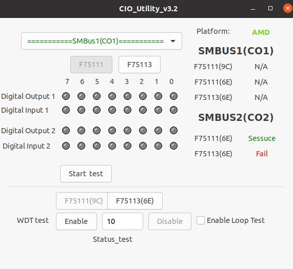
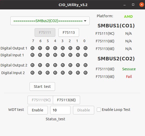
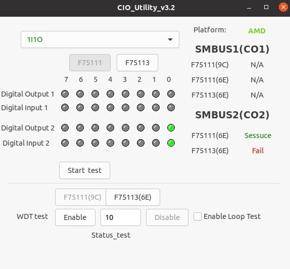
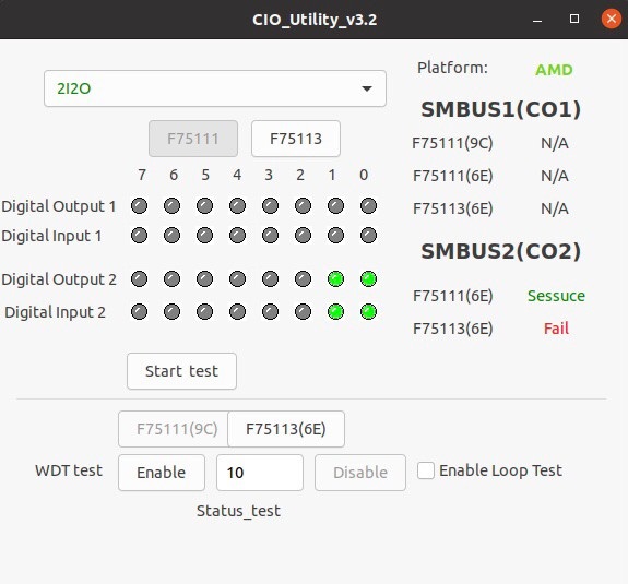
請先看『使用說明』
IO Device:F75111 CIO Utility under Linux
From LEXWiKi
(→The Sample code source you can download from) |
|||
| (4 intermediate revisions not shown.) | |||
| Line 1: | Line 1: | ||
[[Category:AllowPages]] | [[Category:AllowPages]] | ||
== The Sample code source you can download from == | == The Sample code source you can download from == | ||
| - | + | <!-- | |
<Google Drive> | <Google Drive> | ||
| - | Source file: [https://drive.google.com/file/d/ | + | Source file: [https://drive.google.com/file/d/1nqB9Efy2yZgIHYIxjyMfksTZin49-qjo/view?usp=sharing CIO_Utility_v3.2.3_L_Src] |
| - | Binary file: [https://drive.google.com/file/d/ | + | Binary file: [https://drive.google.com/file/d/1XJTow6JCwMFnt-iqBPr-A8mjQ61YtZmZ/view?usp=sharing CIO_Utility_v3.2.3_L_Bin_x64] |
| + | --> | ||
<FTP> | <FTP> | ||
| - | Source file: [ftp://ftp.lex.com.tw/Engineer/SoftSupport/AP_Module/CIO_Uitlity/linux_base/CIO_Utility_Src_v3.2. | + | Source file: [ftp://ftp.lex.com.tw/Engineer/SoftSupport/AP_Module/CIO_Uitlity/linux_base/CIO_Utility_Src_v3.2.3_L.tar.xz CIO_Utility_v3.2.3_L_Src] |
| - | Binary file: [ftp://ftp.lex.com.tw/Engineer/SoftSupport/AP_Module/CIO_Uitlity/linux_base/CIO_Utility_Bin_v3.2. | + | Binary file: [ftp://ftp.lex.com.tw/Engineer/SoftSupport/AP_Module/CIO_Uitlity/linux_base/CIO_Utility_Bin_v3.2.3_L_x64.tar.xz CIO_Utility_v3.2.3_L_Bin_x64] |
== MB Support List== | == MB Support List== | ||
Current revision
Contents |
The Sample code source you can download from
<FTP>
Source file: CIO_Utility_v3.2.3_L_Src
Binary file: CIO_Utility_v3.2.3_L_Bin_x64
MB Support List
| Ivybridge | BayTrail | Apollo Lake | Skylake/Kabylake | Coffee Lake | Whiskey Lake | AMD | Card | Elkhart Lake |
|---|---|---|---|---|---|---|---|---|
|
2I847H 3I847A/D/CW/NX/NM/HW 3I770A/CW CI847A/C CI770A/C |
1I385A/H 1I386H 2I380A 2I385A/CW 2I380NX 2I385BW/EW/HW/PW 2I386EW 2I382A 2I382DW 3I380A/CW/NX ST385W/AW/CW |
2I390CW 2I392CW 3I390AW 3I390NX 3I393NX PM390CW |
2I610DW/HW 2I612CW 3I610DW 3I612DW 3I170DW/HW/NX ST610W CI170A/C PM610DW PM170DW |
CI370DW |
2I810D 3I810DW |
3A100DW |
CIO116-G E691A |
2I640DW |
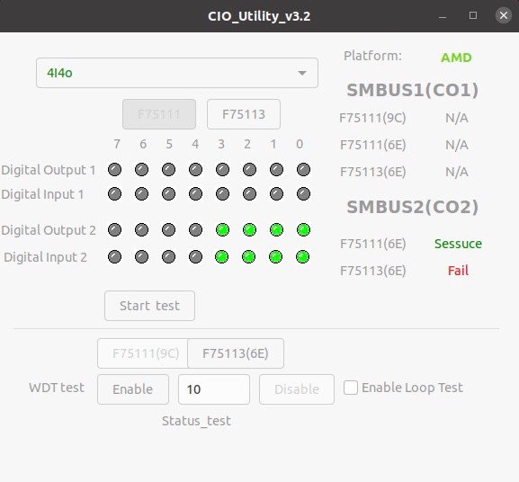
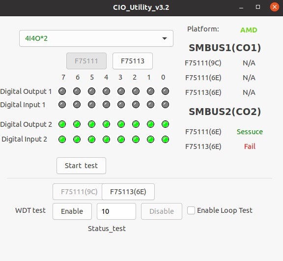
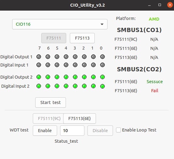
How to use this Demo Application
Before executing the program began, Please switch to the highest authority , continued second F75111 ,chmod 777 and root: \
- Platform will detect intel/AMD , if not get SMbus signal show N/A
- If get SMBUS1/SMBUS2 F75111/F75113 will show Sessuce ,IC not get will show Fail , Not get SMBUS1/SMBUS2 signal will show N/A
1. Press the select your test F75111 or F75113
2. select your test SMBus1(CO1)/SMBus2(CO2) "2i2o","4i4o","4i4o*2","CIO116","8I(CIO1)+8O(CIO2)","1I1O"
3. start button,select single mode or looptest
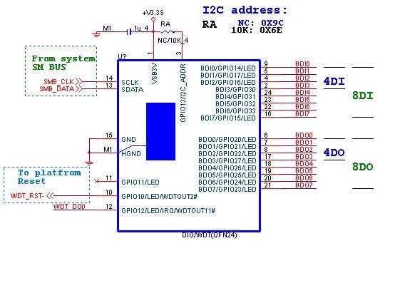
F75111 Layout Picture
Introduction
Initial Internal F75111 port address (0x9c)
   define GPIO1X, GPIO2X, GPIO3X to input or output
   and Enable WDT function pin
Set F75111 DI/DO ( sample code as below Get Input value/Set output value )
   DO: InterDigitalOutput(BYTE byteValue))
   DI: InterDigitalInput()
PULSE mode
Sample to setting GP33, 32, 31, 30 output 1mS low pulse signal.
{
    this->Write_Byte(F75111_INTERNAL_ADDR, GPIO3X_PULSE_CONTROL,       0x00);             //This is setting low pulse output
    this->Write_Byte(F75111_INTERNAL_ADDR, GPIO3X_PULSE_WIDTH_CONTROL, 0x01);             //This selects the pulse width to 1mS
    this->Write_Byte(F75111_INTERNAL_ADDR, GPIO3X_CONTROL_MODE,        0x0F);             //This is setting the GP33, 32, 31, 30 to output function.
    this->Write_Byte(F75111_INTERNAL_ADDR, GPIO3X_Output_Data ,        0x0F);             //This is setting the GP33, 32, 31, 30 output data.
}
Initial internal F75111
void F75111::InitInternalF75111()
{
    this->Write_Byte(F75111_INTERNAL_ADDR,GPIO1X_CONTROL_MODE  ,0x00);        //set GPIO1X to Input  function
    this->Write_Byte(F75111_INTERNAL_ADDR,GPIO3X_CONTROL_MODE  ,0x00);        //set GPIO3X to Input  function
    this->Write_Byte(F75111_INTERNAL_ADDR,GPIO2X_CONTROL_MODE  ,0xFF);        //set GPIO2X to Output function

    this->Write_Byte(F75111_INTERNAL_ADDR,GPIO2X_OUTPUT_DRIVING,0xFF);        //set GPIO2X to Output Drving

    this->Write_Byte(F75111_INTERNAL_ADDR,F75111_CONFIGURATION, 0x03);        //Enable WDT OUT function
}
Set output value
void F75111::InterDigitalOutput(BYTE byteValue)
{
     BYTE byteData = 0;
     byteData = (byteData & 0x01 )? byteValue + 0x01 : byteValue;
     byteData = (byteData & 0x02 )? byteValue + 0x02 : byteValue;
     byteData = (byteData & 0x04 )? byteValue + 0x04 : byteValue;
     byteData = (byteData & 0x80 )? byteValue + 0x08 : byteValue;
     byteData = (byteData & 0x40 )? byteValue + 0x10 : byteValue;
     byteData = (byteData & 0x20 )? byteValue + 0x20 : byteValue;
     byteData = (byteData & 0x10 )? byteValue + 0x40 : byteValue;
     byteData = (byteData & 0x08 )? byteValue + 0x80 : byteValue;           // get value bit by bit

     this->Write_Byte(F75111_INTERNAL_ADDR,GPIO2X_OUTPUT_DATA,byteData);    // write byteData value via GPIO2X output pin
}
Get Input value
BYTE F75111::InterDigitalInput()
{
    BYTE byteGPIO1X = 0;
    BYTE byteGPIO3X = 0;
    BYTE byteData   = 0;

    this->Read_Byte(F75111_INTERNAL_ADDR,GPIO1X_INPUT_DATA,&byteGPIO1X) ;   // Get value from GPIO1X
    this->Read_Byte(F75111_INTERNAL_ADDR,GPIO3X_INPUT_DATA,&byteGPIO3X) ;   // Get value from GPIO3X

    byteGPIO1X = byteGPIO1X  & 0xF0;                                        // Mask unuseful value
    byteGPIO3X = byteGPIO3X  & 0x0F;                                        // Mask unuseful value

    byteData = ( byteGPIO1X & 0x10 )? byteData + 0x01 : byteData;
    byteData = ( byteGPIO1X & 0x80 )? byteData + 0x02 : byteData;
    byteData = ( byteGPIO1X & 0x40 )? byteData + 0x04 : byteData;
    byteData = ( byteGPIO3X & 0x01 )? byteData + 0x08 : byteData;

    byteData = ( byteGPIO3X & 0x02 )? byteData + 0x10 : byteData;
    byteData = ( byteGPIO3X & 0x04 )? byteData + 0x20 : byteData;
    byteData = ( byteGPIO3X & 0x08 )? byteData + 0x40 : byteData;
    byteData = ( byteGPIO1X & 0x20 )? byteData + 0x80 : byteData;           // Get correct DI value from GPIO1X & GPIO3X

    return byteData;
}
define F75111 pin in F75111.h
//--------------------------------------------------------------------------------------------------------
#define    F75111_INTERNAL_ADDR        0x9C   //  OnBoard  F75111 Chipset
#define    F75111_EXTERNAL_ADDR        0x6E   //  External F75111 Chipset
//--------------------------------------------------------------------------------------------------------
#define    F75111_CONFIGURATION        0x03   //  Configure GPIO13 to WDT2 Function
//--------------------------------------------------------------------------------------------------------
#define    GPIO1X_CONTROL_MODE         0x10   //  Select Output Mode or Input Mode
#define    GPIO2X_CONTROL_MODE         0x20   //  Select GPIO2X Output Mode or Input Mode
#define    GPIO3X_CONTROL_MODE         0x40   //  Select GPIO3X Output Mode or Input Mode
//--------------------------------------------------------------------------------------------------------
#define    GPIO1X_INPUT_DATA           0x12   //  GPIO1X Input Data Register
#define    GPIO2X_INPUT_DATA           0x22   //  GPIO2X Input Data Register
#define    GPIO3X_INPUT_DATA           0x42   //  GPIO3X Input Data Register
//--------------------------------------------------------------------------------------------------------
#define    GPIO1X_OUTPUT_DATA          0x11   //  GPIO1X Output Data Register
#define    GPIO2X_OUTPUT_DATA          0x21   //  GPIO2X Output Data Register
#define    GPIO3X_OUTPUT_DATA          0x41   //  GPIO3X Output Data Register
//--------------------------------------------------------------------------------------------------------
#define    GPIO1X_OUTPUT_DRIVING       0x1B   //  Select GPIO1X Output Driving Enable
#define    GPIO2X_OUTPUT_DRIVING       0x2B   //  Select GPIO2X Output Driving Enable
#define    GPIO3X_OUTPUT_DRIVING       0x4B   //  Select GPIO3X Output Driving Enable
//--------------------------------------------------------------------------------------------------------
#define    GPIO1X_PULSE_CONTROL        0x13   //  GPIO1x Level/Pulse Control Register
                                              //  0:Level Mode
                                              //  1:Pulse Mode
#define    GPIO1X_PULSE_WIDTH_CONTROL  0x14   //  GPIO1x Pulse Width Control Register
#define    GP1_PSWIDTH_500US           0x00   //  When select Pulse mode:	500	us.
#define    GP1_PSWIDTH_1MS             0x01   //  When select Pulse mode:	1	ms.
#define    GP1_PSWIDTH_20MS            0x02   //  When select Pulse mode:	20	ms.
#define    GP1_PSWIDTH_100MS           0x03   //  When select Pulse mode:	100	ms.
//--------------------------------------------------------------------------------------------------------
#define    GPIO2X_PULSE_CONTROL        0x23   //  GPIO2x Level/Pulse Control Register
                                              //  0:Level Mode
                                              //  1:Pulse Mode
#define    GPIO2X_PULSE_WIDTH_CONTROL  0x24   //  GPIO2x Pulse Width Control Register
#define    GP2_PSWIDTH_500US           0x00   //  When select Pulse mode:	500	us.
#define    GP2_PSWIDTH_1MS             0x01   //  When select Pulse mode:	1	ms.
#define    GP2_PSWIDTH_20MS            0x02   //  When select Pulse mode:	20	ms.
#define    GP2_PSWIDTH_100MS           0x03   //  When select Pulse mode:	100	ms.
//--------------------------------------------------------------------------------------------------------
#define    GPIO3X_PULSE_CONTROL        0x43   //  GPIO3x Level/Pulse Control Register
                                              //  0:Level Mode
                                              //  1:Pulse Mode
#define    GPIO3X_Output_Data          0x41   //  GPIO3x Output Data Register
#define    GPIO3X_PULSE_WIDTH_CONTROL  0x44   //  GPIO3x Pulse Width Control Register
#define    GP3_PSWIDTH_500US           0x00   //  When select Pulse mode:	500	us.
#define    GP3_PSWIDTH_1MS             0x01   //  When select Pulse mode:	1	ms.
#define    GP3_PSWIDTH_20MS            0x02   //  When select Pulse mode:	20	ms.
#define    GP3_PSWIDTH_100MS           0x03   //  When select Pulse mode:	100	ms.
//--------------------------------------------------------------------------------------------------------
