請先看『使用說明』
Kk:Sandbox2
From LEXWiKi
(Difference between revisions)
(→get keyboard wParam & lParam) |
(→define F75111 pin in F75111.h) |
||
| (12 intermediate revisions not shown.) | |||
| Line 1: | Line 1: | ||
| + | [[Category:AllowPages]] | ||
== The Sample code source you can download from == | == The Sample code source you can download from == | ||
| - | + | ||
| - | + | Source file: [ftp://ftp.lex.com.tw/Engineer/SoftSupport/AP_Module/CIO_Uitlity/CIO_Utility_Src_32bit.zip CIO_Utility_Src_32bit.zip][ftp://ftp.lex.com.tw/Engineer/SoftSupport/AP_Module/CIO_Uitlity/CIO_Utility_Bin_32bit.zip CIO_Utility_Bin_32bit.zip] | |
| - | == How to | + | |
| - | [[Image: | + | Binary file: [ftp://ftp.lex.com.tw/Engineer/SoftSupport/AP_Module/CIO_Uitlity/CIO_Utility_Src_64bit.zip CIO_Utility_Src_64bit.zip][ftp://ftp.lex.com.tw/Engineer/SoftSupport/AP_Module/CIO_Uitlity/CIO_Utility_Bin_64bit.zip CIO_Utility_Bin_64bit.zip] |
| - | + | ||
| - | + | == How to use this Demo Application == | |
| - | + | ||
| + | [[Image:CIO_Uitlity.jpg]] [[Image:CIO_4i4o.jpg]] [[Image:CIO_2i2o.jpg]] | ||
| + | |||
| + | '''Attention Please:You must be install vcredist_x86.exe when first time you run the F75111_DIO.exe DEMO AP,The vcredist_x86.exe include all required DLL file.''' | ||
| + | |||
| + | 1. Press the select your mode "4i4o" or "2i2o" | ||
| + | |||
| + | 2. start test,select single mode or looptest | ||
| + | |||
== Introduction == | == Introduction == | ||
=== Initial Internal F75111 port address (0x9c)=== | === Initial Internal F75111 port address (0x9c)=== | ||
| Line 13: | Line 22: | ||
=== Set F75111 DI/DO ( sample code as below Get Input value/Set output value )=== | === Set F75111 DI/DO ( sample code as below Get Input value/Set output value )=== | ||
| + | DO: InterDigitalOutput(BYTE byteValue)) | ||
DI: InterDigitalInput() | DI: InterDigitalInput() | ||
| Line 28: | Line 38: | ||
== Initial internal '''F75111''' == | == Initial internal '''F75111''' == | ||
<pre> | <pre> | ||
| - | void | + | void F75111::InitInternalF75111() |
{ | { | ||
| - | + | this->Write_Byte(F75111_INTERNAL_ADDR,GPIO1X_CONTROL_MODE ,0x00); //set GPIO1X to Input function | |
| - | + | this->Write_Byte(F75111_INTERNAL_ADDR,GPIO3X_CONTROL_MODE ,0x00); //set GPIO3X to Input function | |
| - | + | this->Write_Byte(F75111_INTERNAL_ADDR,GPIO2X_CONTROL_MODE ,0xFF); //set GPIO2X to Output function | |
| + | |||
| + | this->Write_Byte(F75111_INTERNAL_ADDR,F75111_CONFIGURATION, 0x03); //Enable WDT OUT function | ||
} | } | ||
</pre> | </pre> | ||
| - | == | + | == Set output value == |
<pre> | <pre> | ||
| - | + | void F75111::InterDigitalOutput(BYTE byteValue) | |
{ | { | ||
| - | + | BYTE byteData = 0; | |
| - | + | byteData = (byteData & 0x01 )? byteValue + 0x01 : byteValue; | |
| - | + | byteData = (byteData & 0x02 )? byteValue + 0x02 : byteValue; | |
| - | + | byteData = (byteData & 0x04 )? byteValue + 0x04 : byteValue; | |
| - | + | byteData = (byteData & 0x80 )? byteValue + 0x08 : byteValue; | |
| - | + | byteData = (byteData & 0x40 )? byteValue + 0x10 : byteValue; | |
| - | + | byteData = (byteData & 0x20 )? byteValue + 0x20 : byteValue; | |
| - | + | byteData = (byteData & 0x10 )? byteValue + 0x40 : byteValue; | |
| + | byteData = (byteData & 0x08 )? byteValue + 0x80 : byteValue; // get value bit by bit | ||
| + | |||
| + | this->Write_Byte(F75111_INTERNAL_ADDR,GPIO2X_OUTPUT_DATA,byteData); // write byteData value via GPIO2X output pin | ||
| + | } | ||
| + | </pre> | ||
| + | == Get Input value == | ||
| + | <pre> | ||
| + | BYTE F75111::InterDigitalInput() | ||
| + | { | ||
| + | BYTE byteGPIO1X = 0; | ||
| + | BYTE byteGPIO3X = 0; | ||
| + | BYTE byteData = 0; | ||
| - | + | this->Read_Byte(F75111_INTERNAL_ADDR,GPIO1X_INPUT_DATA,&byteGPIO1X) ; // Get value from GPIO1X | |
| - | + | this->Read_Byte(F75111_INTERNAL_ADDR,GPIO3X_INPUT_DATA,&byteGPIO3X) ; // Get value from GPIO3X | |
| - | + | ||
| - | + | byteGPIO1X = byteGPIO1X & 0xF0; // Mask unuseful value | |
| - | + | byteGPIO3X = byteGPIO3X & 0x0F; // Mask unuseful value | |
| - | + | ||
| - | + | ||
| - | + | byteData = ( byteGPIO1X & 0x10 )? byteData + 0x01 : byteData; | |
| - | byteData = ( | + | byteData = ( byteGPIO1X & 0x80 )? byteData + 0x02 : byteData; |
| - | + | byteData = ( byteGPIO1X & 0x40 )? byteData + 0x04 : byteData; | |
| - | + | byteData = ( byteGPIO3X & 0x01 )? byteData + 0x08 : byteData; | |
| - | + | ||
| - | return byteData; | + | byteData = ( byteGPIO3X & 0x02 )? byteData + 0x10 : byteData; |
| - | }</pre> | + | byteData = ( byteGPIO3X & 0x04 )? byteData + 0x20 : byteData; |
| - | + | byteData = ( byteGPIO3X & 0x08 )? byteData + 0x40 : byteData; | |
| - | == | + | byteData = ( byteGPIO1X & 0x20 )? byteData + 0x80 : byteData; // Get correct DI value from GPIO1X & GPIO3X |
| + | |||
| + | return byteData; | ||
| + | } | ||
| + | </pre> | ||
| + | ==define F75111 pin in F75111.h == | ||
<pre> | <pre> | ||
| - | + | //-------------------------------------------------------------------------------------------------------- | |
| - | + | #define F75111_INTERNAL_ADDR 0x9C // OnBoard F75111 Chipset | |
| - | + | #define F75111_EXTERNAL_ADDR 0x6E // External F75111 Chipset | |
| - | + | //-------------------------------------------------------------------------------------------------------- | |
| - | + | #define F75111_CONFIGURATION 0x03 // Configure GPIO13 to WDT2 Function | |
| - | + | //-------------------------------------------------------------------------------------------------------- | |
| - | + | #define GPIO1X_CONTROL_MODE 0x10 // Select Output Mode or Input Mode | |
| - | + | #define GPIO2X_CONTROL_MODE 0x20 // Select GPIO2X Output Mode or Input Mode | |
| - | + | #define GPIO3X_CONTROL_MODE 0x40 // Select GPIO3X Output Mode or Input Mode | |
| - | + | //-------------------------------------------------------------------------------------------------------- | |
| - | + | #define GPIO1X_INPUT_DATA 0x12 // GPIO1X Input | |
| - | + | #define GPIO3X_INPUT_DATA 0x42 // GPIO3X Input | |
| - | + | //-------------------------------------------------------------------------------------------------------- | |
| - | + | #define GPIO2X_OUTPUT_DATA 0x21 // GPIO2X Output | |
| - | + | //-------------------------------------------------------------------------------------------------------- | |
| - | + | #define GPIO1X_PULSE_CONTROL 0x13 // GPIO1x Level/Pulse Control Register | |
| - | + | // 0:Level Mode | |
| - | + | // 1:Pulse Mode | |
| - | + | #define GPIO1X_PULSE_WIDTH_CONTROL 0x14 // GPIO1x Pulse Width Control Register | |
| - | + | #define GP1_PSWIDTH_500US 0x00 // When select Pulse mode: 500 us. | |
| - | + | #define GP1_PSWIDTH_1MS 0x01 // When select Pulse mode: 1 ms. | |
| - | + | #define GP1_PSWIDTH_20MS 0x02 // When select Pulse mode: 20 ms. | |
| - | + | #define GP1_PSWIDTH_100MS 0x03 // When select Pulse mode: 100 ms. | |
| - | + | //-------------------------------------------------------------------------------------------------------- | |
| - | + | #define GPIO2X_PULSE_CONTROL 0x23 // GPIO2x Level/Pulse Control Register | |
| - | + | // 0:Level Mode | |
| - | + | // 1:Pulse Mode | |
| - | + | #define GPIO2X_PULSE_WIDTH_CONTROL 0x24 // GPIO2x Pulse Width Control Register | |
| - | + | #define GP2_PSWIDTH_500US 0x00 // When select Pulse mode: 500 us. | |
| - | + | #define GP2_PSWIDTH_1MS 0x01 // When select Pulse mode: 1 ms. | |
| - | + | #define GP2_PSWIDTH_20MS 0x02 // When select Pulse mode: 20 ms. | |
| - | + | #define GP2_PSWIDTH_100MS 0x03 // When select Pulse mode: 100 ms. | |
| - | + | //-------------------------------------------------------------------------------------------------------- | |
| - | + | #define GPIO3X_PULSE_CONTROL 0x43 // GPIO3x Level/Pulse Control Register | |
| - | + | // 0:Level Mode | |
| - | + | // 1:Pulse Mode | |
| - | + | #define GPIO3X_Output_Data 0x41 // GPIO3x Output Data Register | |
| - | + | #define GPIO3X_PULSE_WIDTH_CONTROL 0x44 // GPIO3x Pulse Width Control Register | |
| - | + | #define GP3_PSWIDTH_500US 0x00 // When select Pulse mode: 500 us. | |
| - | + | #define GP3_PSWIDTH_1MS 0x01 // When select Pulse mode: 1 ms. | |
| - | + | #define GP3_PSWIDTH_20MS 0x02 // When select Pulse mode: 20 ms. | |
| - | + | #define GP3_PSWIDTH_100MS 0x03 // When select Pulse mode: 100 ms. | |
| - | + | //-------------------------------------------------------------------------------------------------------- | |
| - | + | ||
| - | + | ||
| - | + | ||
| - | + | ||
| - | + | ||
| - | + | ||
| - | + | ||
| - | + | ||
| - | + | ||
| - | + | ||
| - | + | ||
| - | + | ||
| - | + | ||
| - | + | ||
| - | + | ||
| - | + | ||
| - | + | ||
| - | + | ||
| - | + | ||
| - | + | ||
| - | + | ||
| - | + | ||
| - | + | ||
| - | + | ||
| - | + | ||
| - | + | ||
| - | + | ||
| - | + | ||
| - | + | ||
| - | + | ||
| - | + | ||
| - | + | ||
| - | + | ||
| - | + | ||
| - | + | ||
| - | + | ||
| - | + | ||
| - | + | ||
| - | + | ||
| - | + | ||
| - | + | ||
| - | + | ||
| - | + | ||
| - | + | ||
| - | + | ||
| - | + | ||
| - | + | ||
| - | + | ||
Current revision
Contents |
The Sample code source you can download from
Source file: CIO_Utility_Src_32bit.zipCIO_Utility_Bin_32bit.zip
Binary file: CIO_Utility_Src_64bit.zipCIO_Utility_Bin_64bit.zip
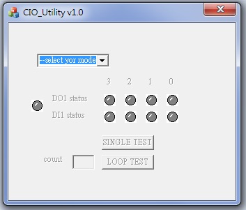
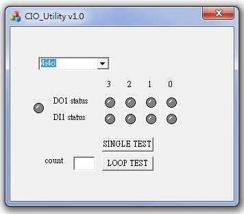
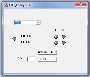
How to use this Demo Application
Attention Please:You must be install vcredist_x86.exe when first time you run the F75111_DIO.exe DEMO AP,The vcredist_x86.exe include all required DLL file.
1. Press the select your mode "4i4o" or "2i2o"
2. start test,select single mode or looptest
Introduction
Initial Internal F75111 port address (0x9c)
   define GPIO1X, GPIO2X, GPIO3X to input or output
   and Enable WDT function pin
Set F75111 DI/DO ( sample code as below Get Input value/Set output value )
   DO: InterDigitalOutput(BYTE byteValue))
   DI: InterDigitalInput()
PULSE mode
Sample to setting GP33, 32, 31, 30 output 1mS low pulse signal.
{
    this->Write_Byte(F75111_INTERNAL_ADDR, GPIO3X_PULSE_CONTROL,       0x00);             //This is setting low pulse output
    this->Write_Byte(F75111_INTERNAL_ADDR, GPIO3X_PULSE_WIDTH_CONTROL, 0x01);             //This selects the pulse width to 1mS
    this->Write_Byte(F75111_INTERNAL_ADDR, GPIO3X_CONTROL_MODE,        0x0F);             //This is setting the GP33, 32, 31, 30 to output function.
    this->Write_Byte(F75111_INTERNAL_ADDR, GPIO3X_Output_Data ,        0x0F);             //This is setting the GP33, 32, 31, 30 output data.
}
Initial internal F75111
void F75111::InitInternalF75111()
{
    this->Write_Byte(F75111_INTERNAL_ADDR,GPIO1X_CONTROL_MODE  ,0x00);        //set GPIO1X to Input  function
    this->Write_Byte(F75111_INTERNAL_ADDR,GPIO3X_CONTROL_MODE  ,0x00);        //set GPIO3X to Input  function
    this->Write_Byte(F75111_INTERNAL_ADDR,GPIO2X_CONTROL_MODE  ,0xFF);        //set GPIO2X to Output function

    this->Write_Byte(F75111_INTERNAL_ADDR,F75111_CONFIGURATION, 0x03);        //Enable WDT OUT function
}
Set output value
void F75111::InterDigitalOutput(BYTE byteValue)
{
     BYTE byteData = 0;
     byteData = (byteData & 0x01 )? byteValue + 0x01 : byteValue;
     byteData = (byteData & 0x02 )? byteValue + 0x02 : byteValue;
     byteData = (byteData & 0x04 )? byteValue + 0x04 : byteValue;
     byteData = (byteData & 0x80 )? byteValue + 0x08 : byteValue;
     byteData = (byteData & 0x40 )? byteValue + 0x10 : byteValue;
     byteData = (byteData & 0x20 )? byteValue + 0x20 : byteValue;
     byteData = (byteData & 0x10 )? byteValue + 0x40 : byteValue;
     byteData = (byteData & 0x08 )? byteValue + 0x80 : byteValue;           // get value bit by bit

     this->Write_Byte(F75111_INTERNAL_ADDR,GPIO2X_OUTPUT_DATA,byteData);    // write byteData value via GPIO2X output pin
}
Get Input value
BYTE F75111::InterDigitalInput()
{
    BYTE byteGPIO1X = 0;
    BYTE byteGPIO3X = 0;
    BYTE byteData   = 0;

    this->Read_Byte(F75111_INTERNAL_ADDR,GPIO1X_INPUT_DATA,&byteGPIO1X) ;   // Get value from GPIO1X
    this->Read_Byte(F75111_INTERNAL_ADDR,GPIO3X_INPUT_DATA,&byteGPIO3X) ;   // Get value from GPIO3X

    byteGPIO1X = byteGPIO1X  & 0xF0;                                        // Mask unuseful value
    byteGPIO3X = byteGPIO3X  & 0x0F;                                        // Mask unuseful value

    byteData = ( byteGPIO1X & 0x10 )? byteData + 0x01 : byteData;
    byteData = ( byteGPIO1X & 0x80 )? byteData + 0x02 : byteData;
    byteData = ( byteGPIO1X & 0x40 )? byteData + 0x04 : byteData;
    byteData = ( byteGPIO3X & 0x01 )? byteData + 0x08 : byteData;

    byteData = ( byteGPIO3X & 0x02 )? byteData + 0x10 : byteData;
    byteData = ( byteGPIO3X & 0x04 )? byteData + 0x20 : byteData;
    byteData = ( byteGPIO3X & 0x08 )? byteData + 0x40 : byteData;
    byteData = ( byteGPIO1X & 0x20 )? byteData + 0x80 : byteData;           // Get correct DI value from GPIO1X & GPIO3X

    return byteData;
}
define F75111 pin in F75111.h
//--------------------------------------------------------------------------------------------------------
#define    F75111_INTERNAL_ADDR        0x9C   //  OnBoard  F75111 Chipset
#define    F75111_EXTERNAL_ADDR        0x6E   //  External F75111 Chipset
//--------------------------------------------------------------------------------------------------------
#define    F75111_CONFIGURATION        0x03   //  Configure GPIO13 to WDT2 Function
//--------------------------------------------------------------------------------------------------------
#define    GPIO1X_CONTROL_MODE         0x10   //  Select Output Mode or Input Mode
#define    GPIO2X_CONTROL_MODE         0x20   //  Select GPIO2X Output Mode or Input Mode
#define    GPIO3X_CONTROL_MODE         0x40   //  Select GPIO3X Output Mode or Input Mode
//--------------------------------------------------------------------------------------------------------
#define    GPIO1X_INPUT_DATA           0x12   //  GPIO1X Input
#define    GPIO3X_INPUT_DATA           0x42   //  GPIO3X Input
//--------------------------------------------------------------------------------------------------------
#define    GPIO2X_OUTPUT_DATA          0x21   //  GPIO2X Output
//--------------------------------------------------------------------------------------------------------
#define    GPIO1X_PULSE_CONTROL        0x13   //  GPIO1x Level/Pulse Control Register
                                              //  0:Level Mode
                                              //  1:Pulse Mode
#define    GPIO1X_PULSE_WIDTH_CONTROL  0x14   //  GPIO1x Pulse Width Control Register
#define    GP1_PSWIDTH_500US           0x00   //  When select Pulse mode:	500	us.
#define    GP1_PSWIDTH_1MS             0x01   //  When select Pulse mode:	1	ms.
#define    GP1_PSWIDTH_20MS            0x02   //  When select Pulse mode:	20	ms.
#define    GP1_PSWIDTH_100MS           0x03   //  When select Pulse mode:	100	ms.
//--------------------------------------------------------------------------------------------------------
#define    GPIO2X_PULSE_CONTROL        0x23   //  GPIO2x Level/Pulse Control Register
                                              //  0:Level Mode
                                              //  1:Pulse Mode
#define    GPIO2X_PULSE_WIDTH_CONTROL  0x24   //  GPIO2x Pulse Width Control Register
#define    GP2_PSWIDTH_500US           0x00   //  When select Pulse mode:	500	us.
#define    GP2_PSWIDTH_1MS             0x01   //  When select Pulse mode:	1	ms.
#define    GP2_PSWIDTH_20MS            0x02   //  When select Pulse mode:	20	ms.
#define    GP2_PSWIDTH_100MS           0x03   //  When select Pulse mode:	100	ms.
//--------------------------------------------------------------------------------------------------------
#define    GPIO3X_PULSE_CONTROL        0x43   //  GPIO3x Level/Pulse Control Register
                                              //  0:Level Mode
                                              //  1:Pulse Mode
#define    GPIO3X_Output_Data          0x41   //  GPIO3x Output Data Register
#define    GPIO3X_PULSE_WIDTH_CONTROL  0x44   //  GPIO3x Pulse Width Control Register
#define    GP3_PSWIDTH_500US           0x00   //  When select Pulse mode:	500	us.
#define    GP3_PSWIDTH_1MS             0x01   //  When select Pulse mode:	1	ms.
#define    GP3_PSWIDTH_20MS            0x02   //  When select Pulse mode:	20	ms.
#define    GP3_PSWIDTH_100MS           0x03   //  When select Pulse mode:	100	ms.
//--------------------------------------------------------------------------------------------------------


