請先看『使用說明』
IO Device:F75111 CIO Utility Console under linux
From LEXWiKi
(Difference between revisions)
(→How to use this Demo Application) |
|||
| Line 1: | Line 1: | ||
| + | [[Category:AllowPages]] | ||
== The Sample code source you can download from == | == The Sample code source you can download from == | ||
Revision as of 00:46, 6 October 2014
Contents |
The Sample code source you can download from
Source file: CIO_Utility_Console_L_Src.tar.bz2
Binary file: CIO_Utility_console_L_Bin.tar.bz2
How to use this Demo Application

1. The program must control I/O device, when you use this you must change user to root, you can use this command "sudo su"
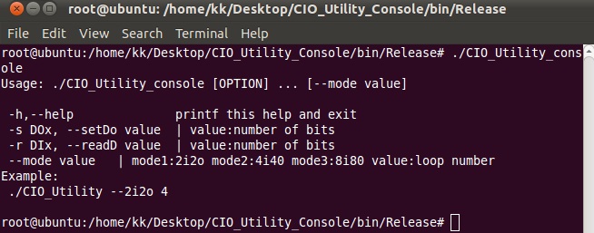
2.enter "./CIO_Utility_console -h"show help function
Example:
CIO_Utility_console --4i4o 1
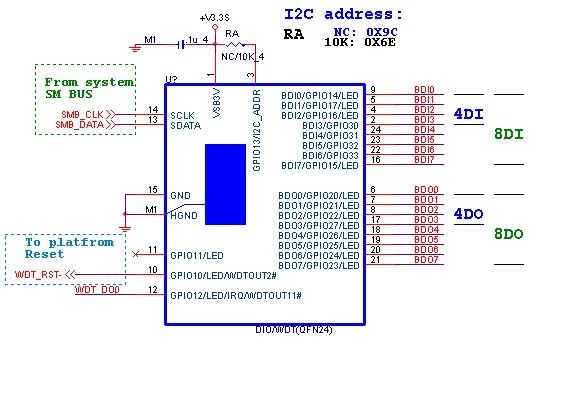
F75111 Layout Picture
Introduction
Initial Internal F75111 port address (0x9c)
   define GPIO1X, GPIO2X, GPIO3X to input or output
   and Enable WDT function pin
Set F75111 DI/DO ( sample code as below Get Input value/Set output value )
   DO: InterDigitalOutput(BYTE byteValue))
   DI: InterDigitalInput()
PULSE mode
Sample to setting GP33, 32, 31, 30 output 1mS low pulse signal.
{
    this->Write_Byte(F75111_INTERNAL_ADDR, GPIO3X_PULSE_CONTROL,       0x00);             //This is setting low pulse output
    this->Write_Byte(F75111_INTERNAL_ADDR, GPIO3X_PULSE_WIDTH_CONTROL, 0x01);             //This selects the pulse width to 1mS
    this->Write_Byte(F75111_INTERNAL_ADDR, GPIO3X_CONTROL_MODE,        0x0F);             //This is setting the GP33, 32, 31, 30 to output function.
    this->Write_Byte(F75111_INTERNAL_ADDR, GPIO3X_Output_Data ,        0x0F);             //This is setting the GP33, 32, 31, 30 output data.
}
Initial internal F75111
void F75111::InitInternalF75111()
{
    this->Write_Byte(F75111_INTERNAL_ADDR,GPIO1X_CONTROL_MODE  ,0x00);        //set GPIO1X to Input  function
    this->Write_Byte(F75111_INTERNAL_ADDR,GPIO3X_CONTROL_MODE  ,0x00);        //set GPIO3X to Input  function
    this->Write_Byte(F75111_INTERNAL_ADDR,GPIO2X_CONTROL_MODE  ,0xFF);        //set GPIO2X to Output function

    this->Write_Byte(F75111_INTERNAL_ADDR,F75111_CONFIGURATION, 0x03);        //Enable WDT OUT function
}
Set output value
void F75111::InterDigitalOutput(BYTE byteValue)
{
     BYTE byteData = 0;
     byteData = (byteData & 0x01 )? byteValue + 0x01 : byteValue;
     byteData = (byteData & 0x02 )? byteValue + 0x02 : byteValue;
     byteData = (byteData & 0x04 )? byteValue + 0x04 : byteValue;
     byteData = (byteData & 0x80 )? byteValue + 0x08 : byteValue;
     byteData = (byteData & 0x40 )? byteValue + 0x10 : byteValue;
     byteData = (byteData & 0x20 )? byteValue + 0x20 : byteValue;
     byteData = (byteData & 0x10 )? byteValue + 0x40 : byteValue;
     byteData = (byteData & 0x08 )? byteValue + 0x80 : byteValue;           // get value bit by bit

     this->Write_Byte(F75111_INTERNAL_ADDR,GPIO2X_OUTPUT_DATA,byteData);    // write byteData value via GPIO2X output pin
}
Get Input value
BYTE F75111::InterDigitalInput()
{
    BYTE byteGPIO1X = 0;
    BYTE byteGPIO3X = 0;
    BYTE byteData   = 0;

    this->Read_Byte(F75111_INTERNAL_ADDR,GPIO1X_INPUT_DATA,&byteGPIO1X) ;   // Get value from GPIO1X
    this->Read_Byte(F75111_INTERNAL_ADDR,GPIO3X_INPUT_DATA,&byteGPIO3X) ;   // Get value from GPIO3X

    byteGPIO1X = byteGPIO1X  & 0xF0;                                        // Mask unuseful value
    byteGPIO3X = byteGPIO3X  & 0x0F;                                        // Mask unuseful value

    byteData = ( byteGPIO1X & 0x10 )? byteData + 0x01 : byteData;
    byteData = ( byteGPIO1X & 0x80 )? byteData + 0x02 : byteData;
    byteData = ( byteGPIO1X & 0x40 )? byteData + 0x04 : byteData;
    byteData = ( byteGPIO3X & 0x01 )? byteData + 0x08 : byteData;

    byteData = ( byteGPIO3X & 0x02 )? byteData + 0x10 : byteData;
    byteData = ( byteGPIO3X & 0x04 )? byteData + 0x20 : byteData;
    byteData = ( byteGPIO3X & 0x08 )? byteData + 0x40 : byteData;
    byteData = ( byteGPIO1X & 0x20 )? byteData + 0x80 : byteData;           // Get correct DI value from GPIO1X & GPIO3X

    return byteData;
}
define F75111 pin in F75111.h
//--------------------------------------------------------------------------------------------------------
#define    F75111_INTERNAL_ADDR        0x9C   //  OnBoard  F75111 Chipset
#define    F75111_EXTERNAL_ADDR        0x6E   //  External F75111 Chipset
//--------------------------------------------------------------------------------------------------------
#define    F75111_CONFIGURATION        0x03   //  Configure GPIO13 to WDT2 Function
//--------------------------------------------------------------------------------------------------------
#define    GPIO1X_CONTROL_MODE         0x10   //  Select Output Mode or Input Mode
#define    GPIO2X_CONTROL_MODE         0x20   //  Select GPIO2X Output Mode or Input Mode
#define    GPIO3X_CONTROL_MODE         0x40   //  Select GPIO3X Output Mode or Input Mode
//--------------------------------------------------------------------------------------------------------
#define    GPIO1X_INPUT_DATA           0x12   //  GPIO1X Input
#define    GPIO3X_INPUT_DATA           0x42   //  GPIO3X Input
//--------------------------------------------------------------------------------------------------------
#define    GPIO2X_OUTPUT_DATA          0x21   //  GPIO2X Output
//--------------------------------------------------------------------------------------------------------
#define    GPIO1X_PULSE_CONTROL        0x13   //  GPIO1x Level/Pulse Control Register
                                              //  0:Level Mode
                                              //  1:Pulse Mode
#define    GPIO1X_PULSE_WIDTH_CONTROL  0x14   //  GPIO1x Pulse Width Control Register
#define    GP1_PSWIDTH_500US           0x00   //  When select Pulse mode:	500	us.
#define    GP1_PSWIDTH_1MS             0x01   //  When select Pulse mode:	1	ms.
#define    GP1_PSWIDTH_20MS            0x02   //  When select Pulse mode:	20	ms.
#define    GP1_PSWIDTH_100MS           0x03   //  When select Pulse mode:	100	ms.
//--------------------------------------------------------------------------------------------------------
#define    GPIO2X_PULSE_CONTROL        0x23   //  GPIO2x Level/Pulse Control Register
                                              //  0:Level Mode
                                              //  1:Pulse Mode
#define    GPIO2X_PULSE_WIDTH_CONTROL  0x24   //  GPIO2x Pulse Width Control Register
#define    GP2_PSWIDTH_500US           0x00   //  When select Pulse mode:	500	us.
#define    GP2_PSWIDTH_1MS             0x01   //  When select Pulse mode:	1	ms.
#define    GP2_PSWIDTH_20MS            0x02   //  When select Pulse mode:	20	ms.
#define    GP2_PSWIDTH_100MS           0x03   //  When select Pulse mode:	100	ms.
//--------------------------------------------------------------------------------------------------------
#define    GPIO3X_PULSE_CONTROL        0x43   //  GPIO3x Level/Pulse Control Register
                                              //  0:Level Mode
                                              //  1:Pulse Mode
#define    GPIO3X_Output_Data          0x41   //  GPIO3x Output Data Register
#define    GPIO3X_PULSE_WIDTH_CONTROL  0x44   //  GPIO3x Pulse Width Control Register
#define    GP3_PSWIDTH_500US           0x00   //  When select Pulse mode:	500	us.
#define    GP3_PSWIDTH_1MS             0x01   //  When select Pulse mode:	1	ms.
#define    GP3_PSWIDTH_20MS            0x02   //  When select Pulse mode:	20	ms.
#define    GP3_PSWIDTH_100MS           0x03   //  When select Pulse mode:	100	ms.
//--------------------------------------------------------------------------------------------------------

