請先看『使用說明』
Kk:Sandbox2
From LEXWiKi
Contents |
The Sample code source you can download from
Source file: CIO_Utility_Src_32bit.zipCIO_Utility_Bin_32bit.zip
Binary file: CIO_Utility_Src_64bit.zipCIO_Utility_Bin_64bit.zip
How to use this Demo Application
Attention Please:You must be install vcredist_x86.exe when first time you run the F75111_DIO.exe DEMO AP,The vcredist_x86.exe include all required DLL file.
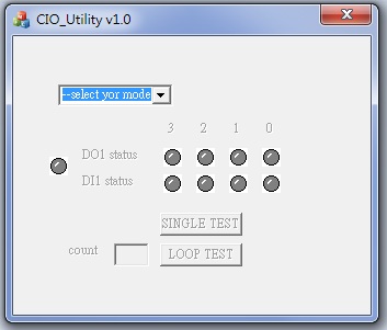
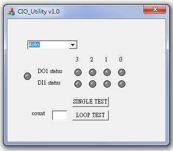
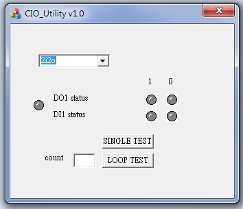
1. Press the select your mode "4i4o" or "2i2o"
2. start test,select single mode or looptest
p.s.
f75111 send "F75111_SetWDTEnable(BYTE byteTimer)" including a parameter "timer",
if there's no disable signal (F75111_SetWDTDisable()) to stop it before timer countdown to 0, System will reboot.
if there's disable signal received, resent Enable WDT signal, for a loop to prevent from reboot
Introduction
Initial Internal F75111 port address (0x9c)
   define GPIO1X, GPIO2X, GPIO3X to input or output
   and Enable WDT function pin
Set F75111 DI/DO ( sample code as below Get Input value/Set output value )
   DO: InterDigitalOutput(BYTE byteValue))
   DI: InterDigitalInput()
Enable/Disable WDT
   Enable : F75111_SetWDTEnable (BYTE byteTimer)
   Disable: F75111_SetWDTDisable ()
PULSE mode
Sample to setting GP33, 32, 31, 30 output 1mS low pulse signal.
{
    this->Write_Byte(F75111_INTERNAL_ADDR, GPIO3X_PULSE_CONTROL,       0x00);             //This is setting low pulse output
    this->Write_Byte(F75111_INTERNAL_ADDR, GPIO3X_PULSE_WIDTH_CONTROL, 0x01);             //This selects the pulse width to 1mS
    this->Write_Byte(F75111_INTERNAL_ADDR, GPIO3X_CONTROL_MODE,        0x0F);             //This is setting the GP33, 32, 31, 30 to output function.
    this->Write_Byte(F75111_INTERNAL_ADDR, GPIO3X_Output_Data ,        0x0F);             //This is setting the GP33, 32, 31, 30 output data.
}
Initial internal F75111
void F75111::InitInternalF75111()
{
    this->Write_Byte(F75111_INTERNAL_ADDR,GPIO1X_CONTROL_MODE  ,0x00);        //set GPIO1X to Input  function
    this->Write_Byte(F75111_INTERNAL_ADDR,GPIO3X_CONTROL_MODE  ,0x00);        //set GPIO3X to Input  function
    this->Write_Byte(F75111_INTERNAL_ADDR,GPIO2X_CONTROL_MODE  ,0xFF);        //set GPIO2X to Output function

    this->Write_Byte(F75111_INTERNAL_ADDR,F75111_CONFIGURATION, 0x03);        //Enable WDT OUT function
}
Set output value
void F75111::InterDigitalOutput(BYTE byteValue)
{
     BYTE byteData = 0;
     byteData = (byteData & 0x01 )? byteValue + 0x01 : byteValue;
     byteData = (byteData & 0x02 )? byteValue + 0x02 : byteValue;
     byteData = (byteData & 0x04 )? byteValue + 0x04 : byteValue;
     byteData = (byteData & 0x80 )? byteValue + 0x08 : byteValue;
     byteData = (byteData & 0x40 )? byteValue + 0x10 : byteValue;
     byteData = (byteData & 0x20 )? byteValue + 0x20 : byteValue;
     byteData = (byteData & 0x10 )? byteValue + 0x40 : byteValue;
     byteData = (byteData & 0x08 )? byteValue + 0x80 : byteValue;           // get value bit by bit

     this->Write_Byte(F75111_INTERNAL_ADDR,GPIO2X_OUTPUT_DATA,byteData);    // write byteData value via GPIO2X output pin
}
Get Input value
BYTE F75111::InterDigitalInput()
{
    BYTE byteGPIO1X = 0;
    BYTE byteGPIO3X = 0;
    BYTE byteData   = 0;

    this->Read_Byte(F75111_INTERNAL_ADDR,GPIO1X_INPUT_DATA,&byteGPIO1X) ;   // Get value from GPIO1X
    this->Read_Byte(F75111_INTERNAL_ADDR,GPIO3X_INPUT_DATA,&byteGPIO3X) ;   // Get value from GPIO3X

    byteGPIO1X = byteGPIO1X  & 0xF0;                                        // Mask unuseful value
    byteGPIO3X = byteGPIO3X  & 0x0F;                                        // Mask unuseful value

    byteData = ( byteGPIO1X & 0x10 )? byteData + 0x01 : byteData;
    byteData = ( byteGPIO1X & 0x80 )? byteData + 0x02 : byteData;
    byteData = ( byteGPIO1X & 0x40 )? byteData + 0x04 : byteData;
    byteData = ( byteGPIO3X & 0x01 )? byteData + 0x08 : byteData;

    byteData = ( byteGPIO3X & 0x02 )? byteData + 0x10 : byteData;
    byteData = ( byteGPIO3X & 0x04 )? byteData + 0x20 : byteData;
    byteData = ( byteGPIO3X & 0x08 )? byteData + 0x40 : byteData;
    byteData = ( byteGPIO1X & 0x20 )? byteData + 0x80 : byteData;           // Get correct DI value from GPIO1X & GPIO3X

    return byteData;
}
Enable WatchDog
void F75111_SetWDTEnable (BYTE byteTimer)
{
    WriteByte(F75111_INTERNAL_ADDR,WDT_TIMER_RANGE  ,byteTimer);                                                       // set WatchDog range and timer
    WriteByte(F75111_INTERNAL_ADDR,WDT_CONFIGURATION,WDT_TIMEOUT_FLAG | WDT_ENABLE | WDT_PULSE | WDT_PSWIDTH_100MS);   // Enable WatchDog, Setting WatchDog configure
}
Disable WatchDog
void F75111_SetWDTDisable ()
{
    WriteByte(F75111_INTERNAL_ADDR,WDT_CONFIGURATION,0x00);                                                            // Disable WatchDog
}
define F75111 pin in F75111.h
//--------------------------------------------------------------------------------------------------------
#define    F75111_INTERNAL_ADDR        0x9C   //  OnBoard  F75111 Chipset
#define    F75111_EXTERNAL_ADDR        0x6E   //  External F75111 Chipset
//--------------------------------------------------------------------------------------------------------
#define    F75111_CONFIGURATION        0x03   //  Configure GPIO13 to WDT2 Function
//--------------------------------------------------------------------------------------------------------
#define    GPIO1X_CONTROL_MODE         0x10   //  Select Output Mode or Input Mode
#define    GPIO2X_CONTROL_MODE         0x20   //  Select GPIO2X Output Mode or Input Mode
#define    GPIO3X_CONTROL_MODE         0x40   //  Select GPIO3X Output Mode or Input Mode
//--------------------------------------------------------------------------------------------------------
#define    GPIO1X_INPUT_DATA           0x12   //  GPIO1X Input
#define    GPIO3X_INPUT_DATA           0x42   //  GPIO3X Input
//--------------------------------------------------------------------------------------------------------
#define    GPIO2X_OUTPUT_DATA          0x21   //  GPIO2X Output
//--------------------------------------------------------------------------------------------------------
#define    GPIO1X_PULSE_CONTROL        0x13   //  GPIO1x Level/Pulse Control Register
                                              //  0:Level Mode
                                              //  1:Pulse Mode
#define    GPIO1X_PULSE_WIDTH_CONTROL  0x14   //  GPIO1x Pulse Width Control Register
#define    GP1_PSWIDTH_500US           0x00   //  When select Pulse mode:	500	us.
#define    GP1_PSWIDTH_1MS             0x01   //  When select Pulse mode:	1	ms.
#define    GP1_PSWIDTH_20MS            0x02   //  When select Pulse mode:	20	ms.
#define    GP1_PSWIDTH_100MS           0x03   //  When select Pulse mode:	100	ms.
//--------------------------------------------------------------------------------------------------------
#define    GPIO2X_PULSE_CONTROL        0x23   //  GPIO2x Level/Pulse Control Register
                                              //  0:Level Mode
                                              //  1:Pulse Mode
#define    GPIO2X_PULSE_WIDTH_CONTROL  0x24   //  GPIO2x Pulse Width Control Register
#define    GP2_PSWIDTH_500US           0x00   //  When select Pulse mode:	500	us.
#define    GP2_PSWIDTH_1MS             0x01   //  When select Pulse mode:	1	ms.
#define    GP2_PSWIDTH_20MS            0x02   //  When select Pulse mode:	20	ms.
#define    GP2_PSWIDTH_100MS           0x03   //  When select Pulse mode:	100	ms.
//--------------------------------------------------------------------------------------------------------
#define    GPIO3X_PULSE_CONTROL        0x43   //  GPIO3x Level/Pulse Control Register
                                              //  0:Level Mode
                                              //  1:Pulse Mode
#define    GPIO3X_Output_Data          0x41   //  GPIO3x Output Data Register
#define    GPIO3X_PULSE_WIDTH_CONTROL  0x44   //  GPIO3x Pulse Width Control Register
#define    GP3_PSWIDTH_500US           0x00   //  When select Pulse mode:	500	us.
#define    GP3_PSWIDTH_1MS             0x01   //  When select Pulse mode:	1	ms.
#define    GP3_PSWIDTH_20MS            0x02   //  When select Pulse mode:	20	ms.
#define    GP3_PSWIDTH_100MS           0x03   //  When select Pulse mode:	100	ms.
//--------------------------------------------------------------------------------------------------------
#define    WDT_TIMER_RANGE             0x37   //  0-255 (secord or minute program by WDT_UNIT)
#define    WDT_CONFIGURATION           0x36   //  Configure WDT Function
#define    WDT_TIMEOUT_FLAG            0x40   //  When watchdog timeout.this bit will be set to 1.
#define    WDT_ENABLE                  0x20   //  Enable watchdog timer
#define    WDT_PULSE                   0x10   //  Configure WDT output mode
                                              //  0:Level Mode
                                              //  1:Pulse Mode

#define    WDT_UNIT                    0x08   //  Watchdog unit select.
                                              //  0:Select second.
                                              //  1:Select minute.

#define    WDT_LEVEL                   0x04   //  When select level output mode:
                                              //  0:Level low
                                              //  1:Level high

#define    WDT_PSWIDTH_1MS             0x00   //  When select Pulse mode:	1	ms.
#define    WDT_PSWIDTH_20MS            0x01   //  When select Pulse mode:	20	ms.
#define    WDT_PSWIDTH_100MS           0x02   //  When select Pulse mode:	100	ms.
#define    WDT_PSWIDTH_4000MS          0x03   //  When select Pulse mode:	4	 s.


