請先看『使用說明』
DPC Module:DPC Console under Linux
From LEXWiKi
The Sample code source you can download form
<FTP>
Binary file: DPC_Console_v1.0.0.4L_Bin_x64
Source file: DPC_Console_v1.0.0.4L_Src_x64
(Include DPC、Light sensor、GPIO module)
Source file: DPC_Console_Simple_Sample
(Only DPC module)
How to compile source code
(Develop Environment: UBUNTU 18.04)
- Step1: Install compile packages
- Install "GCC Ver.7.5.0". You could install "build-essential" include it.
Command: "apt install build-essential".
- Install "gtk2.0".
Command: "apt install libgtk2.0-dev".
- Step2: Compile source code with CodeBlocks.
- Download and install the "CodeBlocks".
Command: "apt-get install codeblocks".
- Open an exist project(DPC_Console.cbp) in CodeBlocks, click the compile button.
- Open an exist project(DPC_Console.cbp) in CodeBlocks, click the compile button.
- Or compile source code with "make"
- cd DPC_Console
- cd DPC_Console
Command: "make".
How to use the DPC console application
- Install resource before execute application. ".\install.sh"
- Execute the application. ".\DPC_Console".
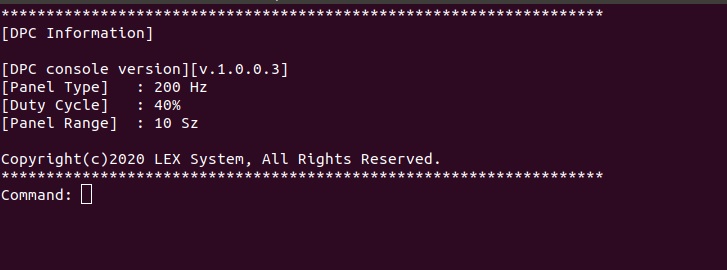
- Dump DPC information with command "-i".
- Print DPC help menu with command "-h".
- Set brightness from 10 to 100 with command "-d". Ex: Set brightness 50 with command "-d50".
- Select panel what you try to adjust with command "-t". Ex: Select 200 Hz with command "-t0".
(0 = 200 Hz, 1 = 275 Hz, 2 = 380 Hz, 3 = 20 Hz, 4 = 25 Hz)
- Select range what you add / subtract brightness with command "-r". Ex: Select 10 Sz with command "-r4".
(0 = 1 Sz, 1 = 2 Sz, 2 = 3 Sz, 3 = 5 Sz, 4 = 10 Sz)
- Step add / subtract brightness with keyboard : "Up arrow key" / "Down arrow key".
- Turn off screen backlight with command "-f". Duty cycle value will be modify to 0.
- Fixed hot key to turn on screen backlight with hot key "Ctrl + n". Duty cycle value will be modify to 50.
- Clear terminal screen with command "Clear".
- Quit DPC application with command "Exit".

If you have LEX light sensor module. How to use light sensor module

- Print light sensor help menu with command "-hl".
- Turn on/off light sensor to modify duty cycle value automaticaly. With command "-la". Ex: Turn off light sensor active with command "-la0".
(0 = Off, 1 = On)
Attention: If active light sensor module, GPIO module will be turned off.
- Select light sensor mode with command "-lm". Ex: Select ALS mode with command "-lm0".
(0 = Measures ALS continuously, 1 = Measures IR continuously)
- Select light sensor range with command "-lr". Ex: Select range 1000 with command "-lr0".
(0 = 1000, 1 = 4000, 2 = 16000, 3 = 64000)
- Turn on/off using custom bounding range with command "-lc". Ex: Turn on custom bounding range with command "-lc1".
(0 = Use, 1 = Not use)
- Set a custom value for light sensor maximum range with command "-lmax". Ex: Set 100 for maximum range with command "-lmax9".
(0 = 10, 1 = 20, 2 = 30, 3 = 40, 4 = 50, 5 = 60, 6 = 70, 7 = 80, 8 = 90, 9 = 100)
- Set a custom value for light sensor median range with command "-lmed". Ex: Set 50 for median range with command "-lmed4".
(0 = 10, 1 = 20, 2 = 30, 3 = 40, 4 = 50, 5 = 60, 6 = 70, 7 = 80, 8 = 90, 9 = 100)
- Set a custom value for light sensor minimum range with command "-lmin". Ex: Set 10 for minimum range with command "-lmin0".
(0 = 10, 1 = 20, 2 = 30, 3 = 40, 4 = 50, 5 = 60, 6 = 70, 7 = 80, 8 = 90, 9 = 100)
Sample code Introduction
Step1. Initial SMBUS.
if( SMBus_Install() == false )
   printf( "Initial SMBUS failed!!! \n" );
Step2. Check DPC device is exist from SMBUS.
#define DPC_ADD 0xb0
if(!SMBus_CheckDevice(DPC_ADDR))
   printf( "DPC device is not exist!!! \n" );
Step3. Setup frequency type of panel.
#define PWMFeq  0x01
BYTE pbCmd = PWMFeq;
(itype = 1: 200 Hz, itype = 2: 275 Hz, itype = 3: 380 Hz, itype = 4: 20 Hz, itype = 5: 25 Hz)
int nValue = itype;
if(SMBus_WriteByte( DPC_ADDR, pbCmd, (BYTE)nValue ) == true)
   printf( "Setup panel type success. \n" );
If you need to get current frequency type of panel.
BYTE byteCmd = PWMFeq;
BYTE byteVale = 0x0;
SMBus_ReadByte(DPC_ADDR, byteCmd, &byteVale);
Step4. Setup DPC brightness level.
BYTE pbCmd = PWMDuty;
(iduty = level 0 ~ 100)
int iduty = 50;
if(SMBus_WriteByte( DPC_ADDR, pbCmd, (BYTE)iduty) == true)
    printf( "Setup brightness level success. \n" );
If you need to get current brightness level.
BYTE byteCmd = PWMDuty;
BYTE byteVale = 0x0;
SMBus_ReadByte(DPC_ADDR, byteCmd, &byteVale);
Final Step. Release SMBUS resource before closing program.
SMBus_Uninstall();
SMBUS.c Introduction
Define SMBus register
 typedef unsigned char  BYTE;
 typedef unsigned short WORD;
 typedef unsigned int   DWORD;
 //----------------------------------------------------------------------------------
 #define SMBHSTSTS     0x00	// SMBus Host Status        Register Offset
 #define SMBHSTCNT     0x02	// SMBus Host Contorl       Register Offset
 #define SMBHSTCMD     0x03	// SMBus Host Command 	    Register Offset
 #define SMBHSTADD     0x04	// SMBus Host Address	    Register Offset
 #define SMBHSTDAT0    0x05	// SMBus Host Data0         Register Offset
 #define SMBHSTCNT_START 0x40   // SMBus Host Contorl -> 0100 0000 Start
 #define SMBHSTCNT_BYTE  0x08   // SMBus Host Contorl -> 0000 1000 Byte Data
 //----------------------------------------------------------------------------------
 #define DPC_ADD       0xb0
 #define PWMFeq        0x01
 #define PWMDuty       0x02
SMBusIoWrite
 void SMBusIoWrite(BYTE byteOffset, BYTE byteData)
 {
     outb( byteData , (g_SMBusMapIoAddr + byteOffset) );
 }
SMBusIoRead
 BYTE SMBusIoRead(BYTE byteOffset)
 {
     DWORD dwAddrVal;
     dwAddrVal = inb((g_SMBusMapIoAddr + byteOffset));
     return (BYTE)(dwAddrVal & 0x0FF);
 }
SMBus_WriteByte
 bool SMBus_WriteByte(BYTE byteSlave, BYTE pCmd, BYTE pByte)
 {
     SMBusIoWrite(SMBHSTADD  , byteSlave & ~1 );
     SMBusIoWrite(SMBHSTCMD  , pCmd );
     SMBusIoWrite(SMBHSTDAT0 , pByte );
     SMBusIoWrite(SMBHSTCNT  , SMBHSTCNT_START | SMBHSTCNT_BYTE);
     return true;
 }
