請先看『使用說明』
IO Device:F81966 LPC DIO under Windows
From LEXWiKi
Contents |
The Sample code source you can download from
<FTP>
Source file: F81966_LPC_GPIO_Utility_Src_v1.6.0.0
Binary file: F81966_LPC_GPIO_Utility_Bin_x86_v1.6.0.0 F81966_LPC_GPIO_Utility_Bin_x64_v1.6.0.0
F81966 DLL : F81966_DLL_v1.1.1_x86 F81966_DLL_v1.1.1_x64
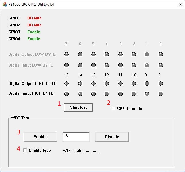
Introduction F81966 DIO
- run as administrator
- Start test Button,Send bits one by one and one by one receive
- CIO116 mode for CIO116 module use
- Set time countdown,If the end of the countdown, the trigger signal to reboot
- Enable loop ,Continuously reset the WDT to ensure that when the system is normal, the restart signal will not be triggered
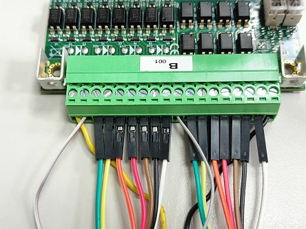
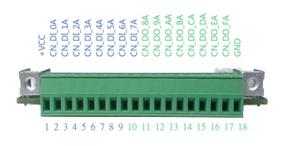
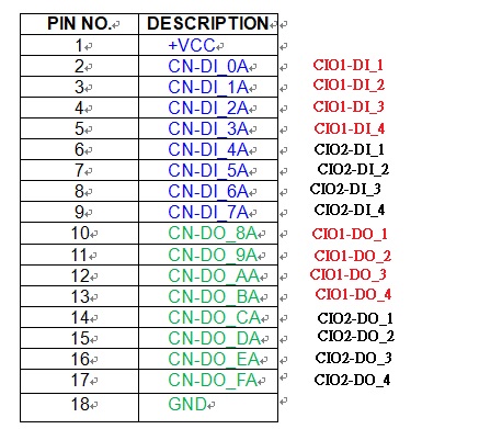
F81966 DIO with CIO116_B
CN-DI_0A(white_red) to CN-DO_8A(white_red)、CN-DI_1A(green) to CN-DO_9A(green)、CN-DI_2A(yellow) to CN-DO_AA(yellow)、CN-DI_3A(orange) to CN-DO_BA(orange)、
CN-DI_4A(red) to CN-DO_CA(red)、CN-DI_5A(brown) to CN-DO_DA(brown)、CN-DI_6A(black) to CN-DO_EA(black)、CN-DI_7A(white) to CN-DO_FA(white).
GND and +VCC connect to power.
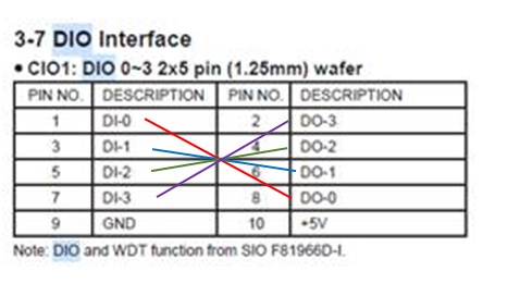
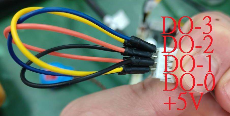
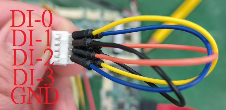
F81966 DIO direct connect
Using 2I130HW to example how to connect.
DI-0(yellow) to DO-0(yellow)、DI-1(black) to DO-1(black)、DI-2(orange) to DO-2(orange)、DI-3(blue) to DO-3(blue).
GND and +5V are empty.
F81966_DLL Function
F81966_DLL_API bool  F81966_LPC_Init(pF81966_status status);

F81966_DLL_API BYTE  F81966_LPC_Digital_Read_LOW();
F81966_DLL_API void  F81966_LPC_Digital_Write_LOW(BYTE byteValue);
F81966_DLL_API BYTE  F81966_LPC_Digital_Read_HIGH();
F81966_DLL_API void  F81966_LPC_Digital_Write_HIGH(BYTE byteValue);

F81966_DLL_API void  F81966_LPC_Set_WDT_Enable(BYTE byteValue);
F81966_DLL_API void  F81966_LPC_Set_WDT_Disable();
Digital Input/Ooutput test
Note when using the following boards:2I110D
CIO1 needs to be controlled by CIO3

sample code
Set CIO1 CIO2 Digital Output all high
F81966_LPC_Digital_Write_LOW(256);

Set CIO1 CIO2 Digital Output all low
F81966_LPC_Digital_Write_LOW(0);

Set CIO1 Digital Output bit 4 high
F81966_LPC_Digital_Write_LOW(16);

Set CIO2 Digital Output bit 10 high
F81966_LPC_Digital_Write_HIGH(4);
Read Din
value = F81966_LPC_Digital_Read_LOW();
Watch Dog test
sample code
Set WDT 10 sec
F81966_LPC_Set_WDT_Enable(10);
Disable WDT
F81966_LPC_Set_WDT_Disable();
