請先看『使用說明』
IO Device:F81966 LPC DIO under Windows console
From LEXWiKi
The Sample code source you can download from
<FTP>
Package file: F81966_DEVELOP_DLL_W_v1.0.5.9
How to use console
Introduction Command List
“-h”: Show help menu about DLL function.
“-exit”: Exit sample program.
“-i”: Initial GPIO module.
“-f”: Free GPIO module.
“-check”: Check F81966 module chip exist or not.
“-c”: CIO port. Support CIO port is defined in Motherboard spec.
“-sd”: Setup GPIO pin status is DI or DO in CIO port.
“-so”: Send DO signal once to trigger pin to high or low in CIO port.
“-gd”: Get current GPIO pin status is DI or DO in CIO port.
“-go”: Get current DO pin trigger status is high or low in CIO port.
“-gi”: Receive current DI pin status.
“-u”: Setup WDT time unit. Value = 0: Second; Value = 1: Minute.
“-we”: Start WDT function and setup countdown seconds.
“-wd”: Stop WDT function.
“-wt”: Query WDT countdown remaining time.
Initial F81966 module
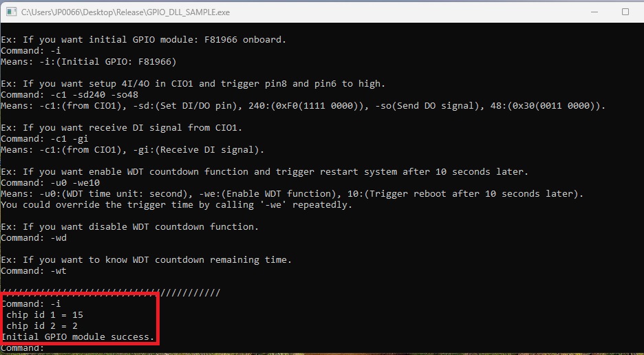
If you want initial GPIO module: F81966 onboard.
Command: -i
Means: -i:(Initial GPIO: F81966 resource)
Free F81966 module
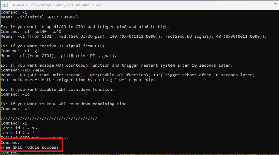
If you want free GPIO module resource.
Command: -f
Means: -f:(Free GPIO: F81966 resource)
Check F81966 chip is exist
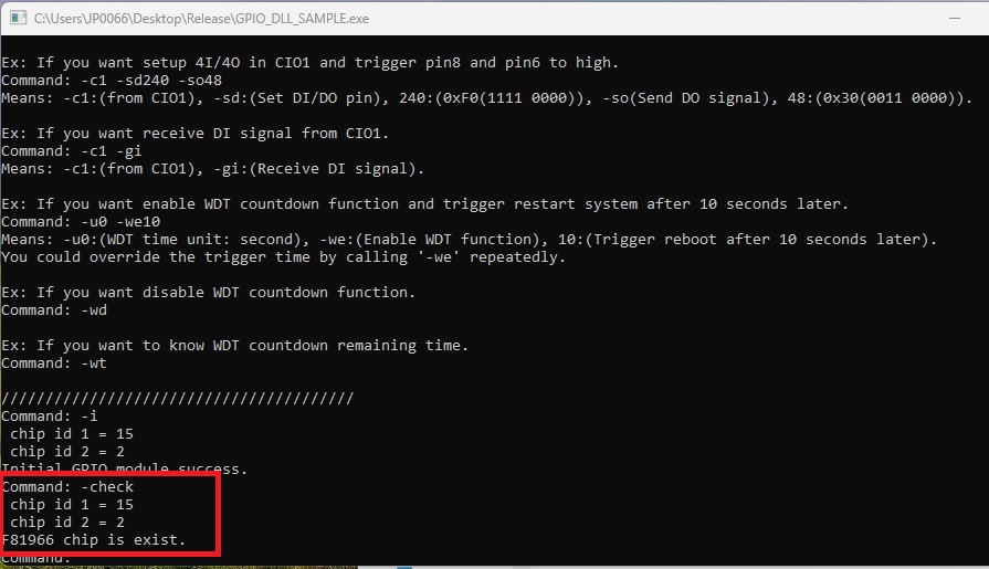
If you want check F81966 module is exist on the device.
Command: -check
Means: -check:(Get F81966 chip ID: 0x1502)
Define GPIO pin status(DI/DO)
Setup GPIO pins status are DI or DO in CIO port.
Use 1 byte to indicate the status of the Pins.
Bit value = 1: pin status is DO; Bit value = 0: pin status is DI.
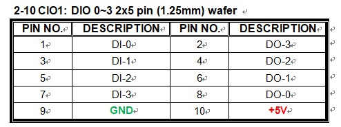
(Pin1 is bit0, Pin3 is bit1, Pin5 is bit2 and Pin7 is bit3)

(Pin8 is bit4, Pin6 is bit5, Pin4 is bit6 and Pin2 is bit7)
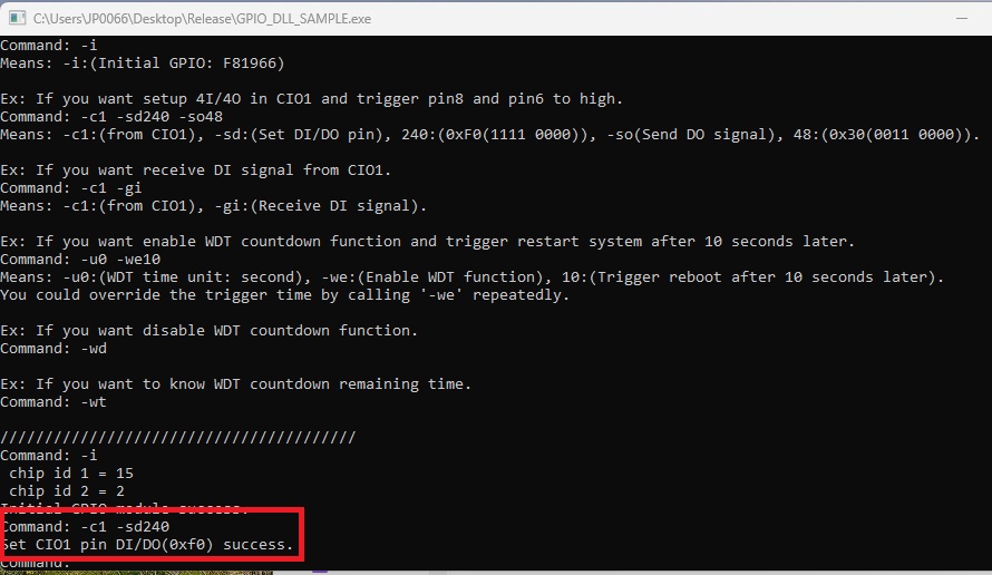
If you want set CIO1 pins status is 4I/4O. (Bits: 0xF0)
Command: -c1 -sd240
Means: -c1:(CIO1), -sd:(set DI/DO), 240:(0xF0(1111 0000))
Trigger DO pin signal to high or low
Set DO pin register value in CIO port to trigger high or low status.
Use 1 byte to indicate the status of the Pins.
Bit value = 1: trigger to High; Bit value = 0:trigger to low.
(Pin1 is bit0, Pin3 is bit1, Pin5 is bit2 and Pin7 is bit3)

(Pin8 is bit4, Pin6 is bit5, Pin4 is bit6 and Pin2 is bit7)
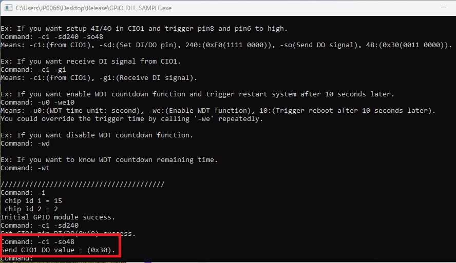
If you want to trigger CIO1 pins pin8 and pin6 to high. (Bits: 0x30)
- Pin which be trigger, status must be DO.
Command: -c1 -so48
Means: -c1:(CIO1), -so(Send DO signal), 48:(0x30(0011 0000))
Receive DI pin current status
Receive DO pin register value from CIO port.
Use 1 byte to indicate the status of the Pins.
Bit value = 1: receive high; Bit value = 0: receive low.
(Pin1 is bit0, Pin3 is bit1, Pin5 is bit2 and Pin7 is bit3)

(Pin8 is bit4, Pin6 is bit5, Pin4 is bit6 and Pin2 is bit7)
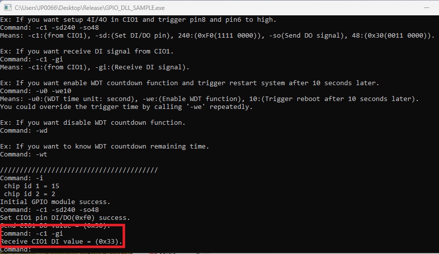
If you want receive CIO1 pins current status.
- Pin status must be DI.
- Attention: DI pin default register value is high. If pin not connect any device, return bits is always high.
Command: -c1 -gi
Means: -c1:(CIO1), -gi:(Receive DI signal)
If return value is 0x33(0011 0011), it means pin1 and pin3 in CIO1 port received high signal.
We only use pin1 and pin3 value, because CIO1 port pin status value is 0xF0(1111 0000)(4I/4O).
Enable Watch Dog Timer to reset system
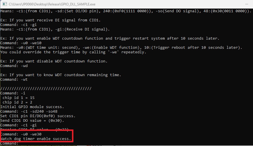
If you want enable WDT countdown function and trigger restart system after 30 seconds later.
- You could override the trigger time by calling '-we' repeatedly.
Command: -u0 –we30
Means: -u:(WDT time unit: second), -we:(Enable WDT function), 30:(Trigger reboot after 30 seconds later)
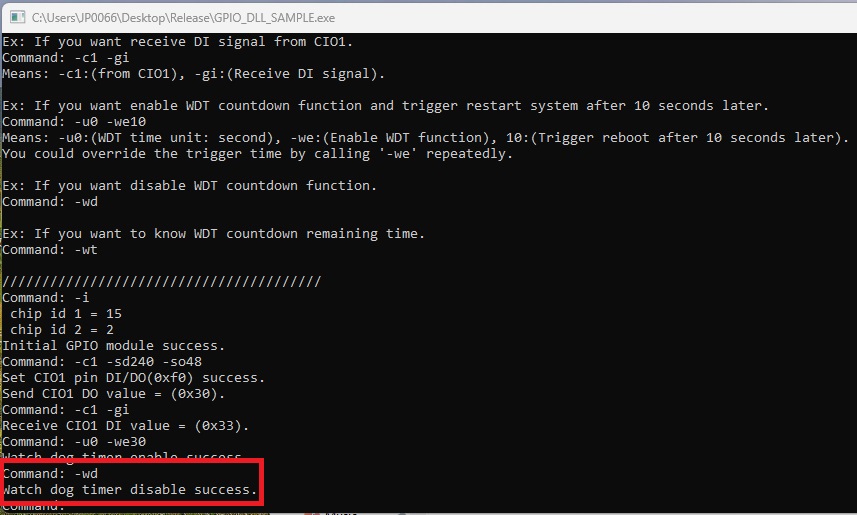
Disable Watch Dog Timer
If you want disable WDT countdown function.
Command: -wd
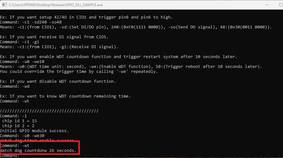
Get Watch Dog Timer countdown time
If you want to know WDT countdown remaining time.
Command: -wt
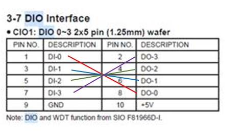
F81966 DIO direct connect
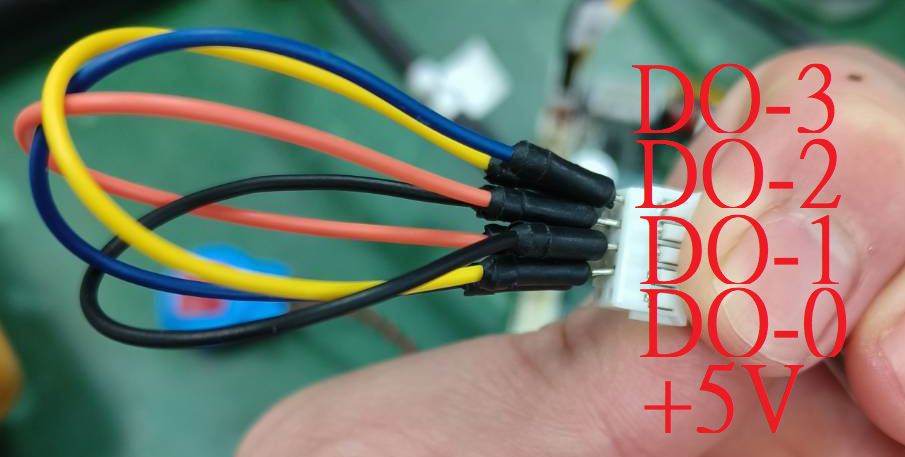
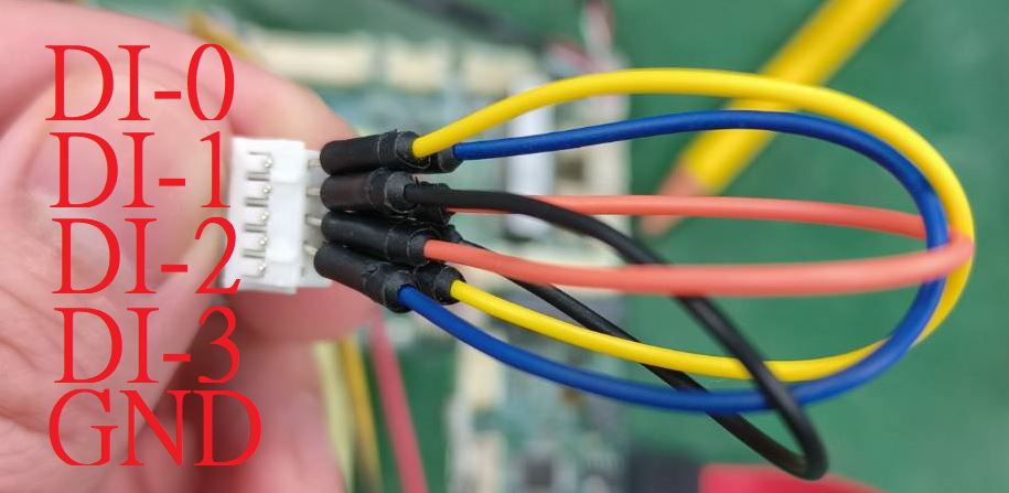
Using 2I130HW to example how to connect.
DI-0(yellow) to DO-0(yellow)、DI-1(black) to DO-1(black)、DI-2(orange) to DO-2(orange)、DI-3(blue) to DO-3(blue).
GND and +5V are empty.
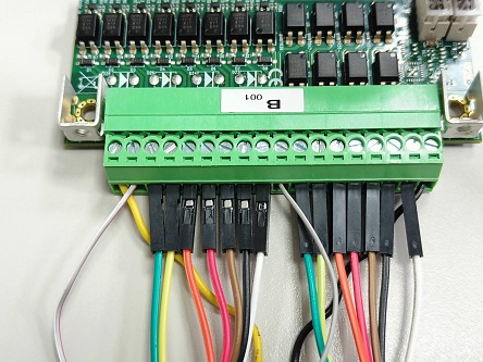
F81966 DIO with CIO116_B
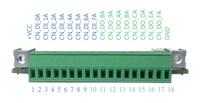
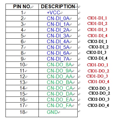
CN-DI_0A(white_red) to CN-DO_8A(white_red)、CN-DI_1A(green) to CN-DO_9A(green)、CN-DI_2A(yellow) to CN-DO_AA(yellow)、CN-DI_3A(orange) to CN-DO_BA(orange)、
CN-DI_4A(red) to CN-DO_CA(red)、CN-DI_5A(brown) to CN-DO_DA(brown)、CN-DI_6A(black) to CN-DO_EA(black)、CN-DI_7A(white) to CN-DO_FA(white).
GND and +VCC connect to power.
F81966_DLL Function
F81966_DLL_API int F81966_DLL_Init();
F81966_DLL_API int F81966_DLL_Free();
F81966_DLL_API int F81966_DLL_CheckDeviceExist();

F81966_DLL_API int F81966_DLL_SetDioPinStatus(int nCioPort, BYTE bDIOBits);
F81966_DLL_API int F81966_DLL_GetDioPinStatus(int nCioPort, BYTE& bDIOBits);

F81966_DLL_API int F81966_DLL_SendDOValue(int nCioPort, BYTE bDOVal);
F81966_DLL_API int F81966_DLL_GetDOValue(int nCioPort, BYTE& bDOVal);
F81966_DLL_API int F81966_DLL_GetDIValue(int nCioPort, BYTE& bDIVal);

F81966_DLL_API int F81966_DLL_StartWatchDogTimer(int nUnit, int nCount);
F81966_DLL_API int F81966_DLL_StopWatchDogTimer();
F81966_DLL_API int F81966_DLL_GetWatchDogCountdown(int& nUnit, int& nCount);
