請先看『使用說明』
IO Device:F81966 LPC DIO under Windows console
From LEXWiKi
(New page: Category:AllowPages == The Sample code source you can download from == <!-- <Google Drive> Source file: [https://drive.google.com/file/d/1sT4srcMQhjyLUyeypxGe-kEPeOdiVyr9/view?usp=sha...) |
(→Introduction F81966 DIO) |
||
| Line 30: | Line 30: | ||
[ftp://ftp.lex.com.tw/Engineer/SoftSupport/AP_Module/F81966_LPC_DIO/windows_base/F81966_DLL_x64_v1.1.1.zip F81966_DLL_v1.1.1_x64 ] | [ftp://ftp.lex.com.tw/Engineer/SoftSupport/AP_Module/F81966_LPC_DIO/windows_base/F81966_DLL_x64_v1.1.1.zip F81966_DLL_v1.1.1_x64 ] | ||
| - | == Introduction | + | == Introduction Command List == |
| - | + | ||
| - | + | “-h”: Show help menu about DLL function.<br> | |
| - | + | “-exit”: Exit sample program.<br> | |
| - | + | “-i”: Initial GPIO module.<br> | |
| - | + | “-f”: Free GPIO module.<br> | |
| - | + | “-check”: Check F81966 module chip exist or not.<br> | |
| + | “-c”: CIO port. Support CIO port is defined in Motherboard spec.<br> | ||
| + | “-sd”: Setup GPIO pin status is DI or DO in CIO port.<br> | ||
| + | “-so”: Send DO signal once to trigger pin to high or low in CIO port.<br> | ||
| + | “-gd”: Get current GPIO pin status is DI or DO in CIO port.<br> | ||
| + | “-go”: Get current DO pin trigger status is high or low in CIO port.<br> | ||
| + | “-gi”: Receive current DI pin status.<br> | ||
| + | “-u”: Setup WDT time unit. Value = 0: Second; Value = 1: Minute.<br> | ||
| + | “-we”: Start WDT function and setup countdown seconds.<br> | ||
| + | “-wd”: Stop WDT function.<br> | ||
| + | “-wt”: Query WDT countdown remaining time.<br> | ||
== F81966 DIO with CIO116_B == | == F81966 DIO with CIO116_B == | ||
Revision as of 16:11, 12 May 2025
Contents |
The Sample code source you can download from
<FTP>
Source file: F81966_LPC_GPIO_Utility_Src_v1.6.0.0
Binary file: F81966_LPC_GPIO_Utility_Bin_x86_v1.6.0.0 F81966_LPC_GPIO_Utility_Bin_x64_v1.6.0.0
F81966 DLL : F81966_DLL_v1.1.1_x86 F81966_DLL_v1.1.1_x64
Introduction Command List
“-h”: Show help menu about DLL function.
“-exit”: Exit sample program.
“-i”: Initial GPIO module.
“-f”: Free GPIO module.
“-check”: Check F81966 module chip exist or not.
“-c”: CIO port. Support CIO port is defined in Motherboard spec.
“-sd”: Setup GPIO pin status is DI or DO in CIO port.
“-so”: Send DO signal once to trigger pin to high or low in CIO port.
“-gd”: Get current GPIO pin status is DI or DO in CIO port.
“-go”: Get current DO pin trigger status is high or low in CIO port.
“-gi”: Receive current DI pin status.
“-u”: Setup WDT time unit. Value = 0: Second; Value = 1: Minute.
“-we”: Start WDT function and setup countdown seconds.
“-wd”: Stop WDT function.
“-wt”: Query WDT countdown remaining time.
F81966 DIO with CIO116_B
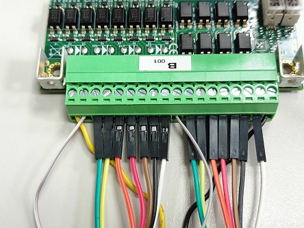
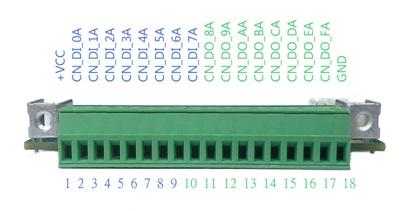
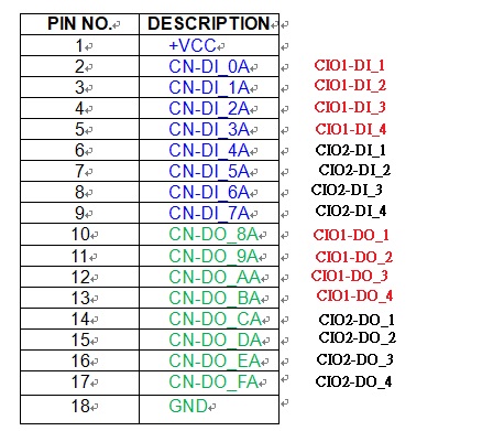
CN-DI_0A(white_red) to CN-DO_8A(white_red)、CN-DI_1A(green) to CN-DO_9A(green)、CN-DI_2A(yellow) to CN-DO_AA(yellow)、CN-DI_3A(orange) to CN-DO_BA(orange)、
CN-DI_4A(red) to CN-DO_CA(red)、CN-DI_5A(brown) to CN-DO_DA(brown)、CN-DI_6A(black) to CN-DO_EA(black)、CN-DI_7A(white) to CN-DO_FA(white).
GND and +VCC connect to power.
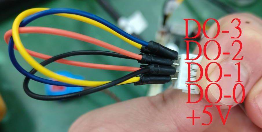
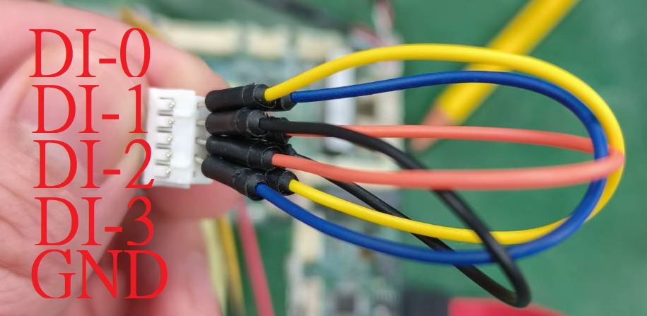
F81966 DIO direct connect
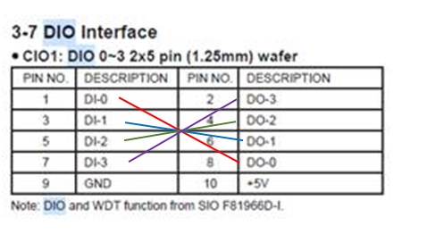
Using 2I130HW to example how to connect.
DI-0(yellow) to DO-0(yellow)、DI-1(black) to DO-1(black)、DI-2(orange) to DO-2(orange)、DI-3(blue) to DO-3(blue).
GND and +5V are empty.
F81966_DLL Function
F81966_DLL_API bool  F81966_LPC_Init(pF81966_status status);

F81966_DLL_API BYTE  F81966_LPC_Digital_Read_LOW();
F81966_DLL_API void  F81966_LPC_Digital_Write_LOW(BYTE byteValue);
F81966_DLL_API BYTE  F81966_LPC_Digital_Read_HIGH();
F81966_DLL_API void  F81966_LPC_Digital_Write_HIGH(BYTE byteValue);

F81966_DLL_API void  F81966_LPC_Set_WDT_Enable(BYTE byteValue);
F81966_DLL_API void  F81966_LPC_Set_WDT_Disable();
Digital Input/Ooutput test
Note when using the following boards:2I110D
CIO1 needs to be controlled by CIO3

sample code
Set CIO1 CIO2 Digital Output all high
F81966_LPC_Digital_Write_LOW(256);

Set CIO1 CIO2 Digital Output all low
F81966_LPC_Digital_Write_LOW(0);

Set CIO1 Digital Output bit 4 high
F81966_LPC_Digital_Write_LOW(16);

Set CIO2 Digital Output bit 10 high
F81966_LPC_Digital_Write_HIGH(4);
Read Din
value = F81966_LPC_Digital_Read_LOW();
Watch Dog test
sample code
Set WDT 10 sec
F81966_LPC_Set_WDT_Enable(10);
Disable WDT
F81966_LPC_Set_WDT_Disable();
